Dynamic Mechanical Strain Transfer and Long Term Elastomer Creep in Sealed Microelectromechanical Sensor Enclosures
Elastomer creep alters baseline compressive stress on MEMS packages, causing long term zero drift that requires digital firmware offset compensation.
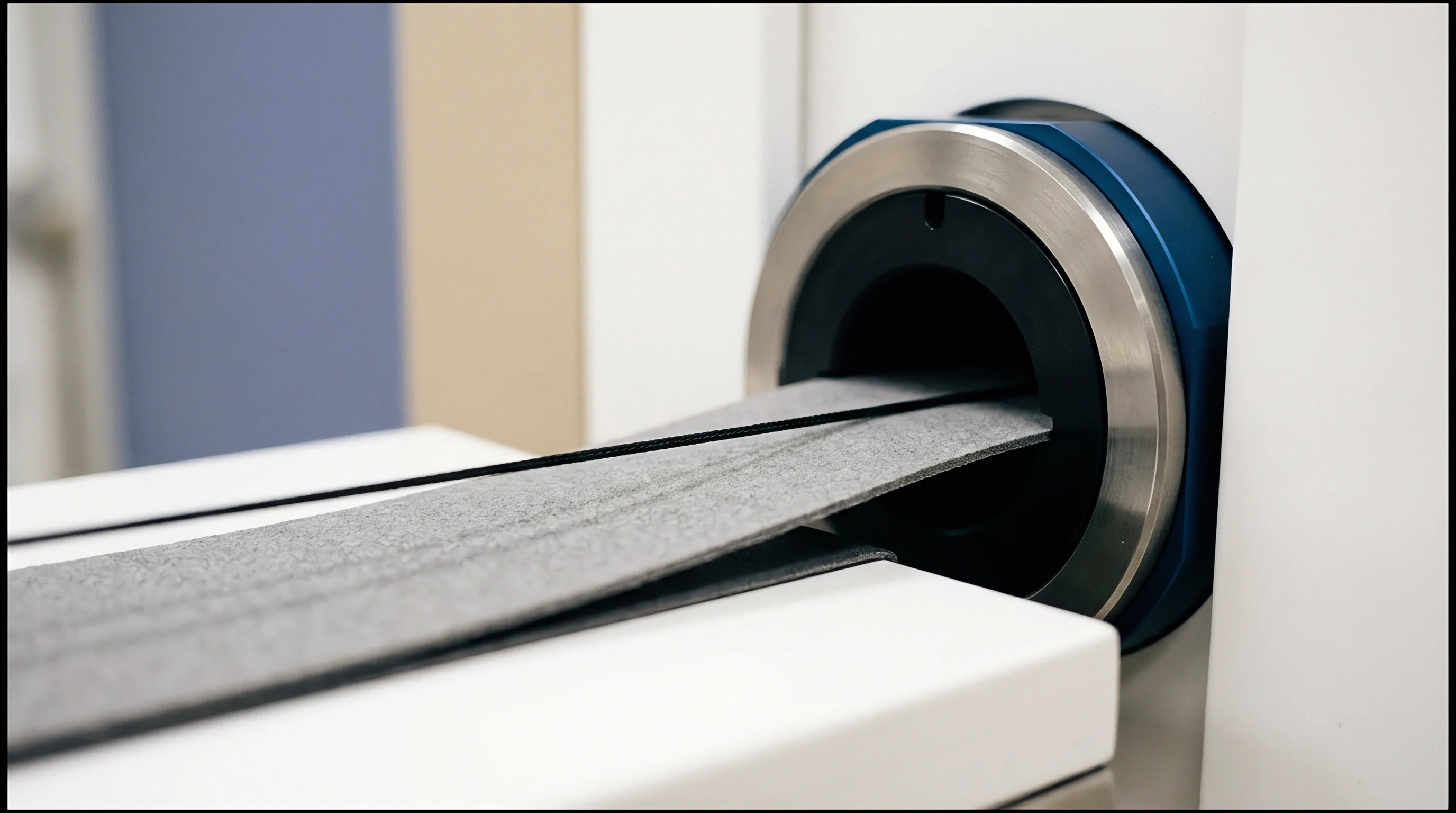

Gasket

Mechanical Strain Transfer Channels
Polymer sealing rings placed between rigid sensor housings and printed circuit boards create physical mechanical pathways. External structural loads, fasteners, and internal ambient pressure variations transfer mechanical force through the seal elastomer to the sensor substrate. Elastomer seals degrade under mechanical stress.
When external shock or vibration acts on a sealed enclosure, the elastomeric seal compresses and shears, transferring fractional strain directly into the surface-mounted sensor package.
The magnitude of mechanical strain transfer depends on the material elastic modulus, Poisson ratio, and gasket geometry. Harder elastomers transfer higher shear stresses. High-durometer elastomers act as rigid mechanical couplings, transmitting enclosure flexure directly into the sensor die.
Conversely, lower durometer materials dissipate mechanical energy through shear deformation within the bulk polymer matrix, reducing parasitic stress on the silicon substrate.
Unsealed or gel-encapsulated microelectromechanical sensor structures exhibit distinct strain transmission modes. Direct mechanical contact between housing walls and gel potting material channels thermal expansion stress straight to the piezoresistive sensing element. Thermal expansion mismatch drives interface strain.
Calculating the total mechanical strain transferred to the silicon substrate involves analyzing the differential thermal expansion coefficients across all housing materials, printed circuit board substrates, and elastomer formulations.
| Elastomer Formulation | Shore A Hardness | Elastic Modulus (MPa) | Poisson Ratio | Strain Transfer Coefficient |
|---|---|---|---|---|
| Fluoroelastomer (FKM) | 75 | 6.8 | 0.48 | 0.72 |
| Nitrile Rubber (NBR) | 70 | 5.2 | 0.47 | 0.61 |
| Silicone Rubber (VMQ) | 50 | 2.1 | 0.49 | 0.34 |
| Fluorosilicone (FVMQ) | 60 | 3.4 | 0.48 | 0.45 |
Gasket geometry dictates stress distribution. O-ring seals under compressive loads produce a non-uniform contact stress profile across the sealing surface. As ambient temperatures shift, differential thermal expansion between aluminum housing walls (coefficient of thermal expansion 23 ppm per degree Celsius) and FR4 board substrates (coefficient of thermal expansion 14 ppm per degree Celsius) creates lateral shear displacement across the compressed gasket cross-section.
This mechanical shear manifests as asymmetric bending force on the sensor die attach pad.

Housing Deformation and Seal Compressive Load
Environmental pressure changes squeeze external structural walls and alter internal mounting geometries. When an enclosure experiences ambient pressure spikes, thin housing walls deflect inward, increasing compression on internal elastomeric seals. O-ring squeeze alters the baseline signal.
This compressive force transmits through PCB trace layers into surface-mount packages, perturbing internal piezoresistive bridge balances.
Thicker gasket cross-sections distribute external housing flexure across a larger volume and reduce parasitic mechanical coupling to the silicon substrate.
Designers prevent excessive strain coupling by enforcing mechanical isolation zones around sensitive sensor footprints. Mechanical isolation channels cut into circuit board layers prevent board flexure forces from reaching sensor lands. Mechanical strain paths in sealed enclosures comprise several specific transmission channels:
- Shear Strain Coupling ~ External housing twisting loads transmit through elastomeric gasket faces directly to PCB mounting pads.
- Gel Thermal Expansion ~ Silicone potting materials expand against rigid internal walls, applying compressive force to sensitive MEMS diaphragms.
- Differential CTE Mismatch ~ Aluminum enclosure walls expand faster than silicon substrates, straining the perimeter O-ring seal line.
- Asymmetric Gasket Squeeze ~ Non-uniform bolt torque deforms seal profiles unequally, inducing tilt in surface-mounted sensor packages.
Ignoring mechanical strain paths across environmental seals leads to permanent zero-point drift and invalidates field accuracy guarantees.


Creep
Viscoelastic Stress Relaxation Kinetics
Polymer chain relaxation under sustained mechanical stress causes continuous decay in contact pressure. Over extended operating periods, compressed elastomeric gaskets suffer viscoelastic stress relaxation, reducing initial seal compression force while shifting internal stress balances. Creep reduces the initial preload.
As the polymer matrix undergoes molecular rearrangement, initial compressive strain converts into permanent set, altering mechanical boundary conditions applied to the enclosed microelectromechanical package.
Temperature spikes accelerate polymer chain relaxation. Operating temperatures above 85 degrees Celsius break temporary physical crosslinks in fluoroelastomer and silicone matrices, accelerating viscoelastic creep rate according to Arrhenius kinetics. Creep compliance increases over operational time.
High thermal stress combined with static mechanical load accelerates zero-point offset drift in pressure and inertial sensors.
| Elastomer Type | Initial Stress (MPa) | Relaxated Stress at 1000h (MPa) | Compression Set (Percent) | Activation Energy (kJ/mol) |
|---|---|---|---|---|
| Fluoroelastomer (FKM) | 4.50 | 3.15 | 14.2 | 82.4 |
| Nitrile Rubber (NBR) | 3.80 | 2.28 | 22.5 | 68.1 |
| Silicone Rubber (VMQ) | 1.90 | 1.42 | 11.8 | 91.3 |
| Fluorosilicone (FVMQ) | 2.60 | 1.77 | 16.4 | 78.9 |
Quantifying stress relaxation requires measuring force retention over time under continuous compressive deformation. Mathematical modeling of viscoelastic behavior relies on Prony series expansions of the relaxation modulus. The relaxation modulus decay function combines multiple discrete Maxwell elements in parallel, representing fast short-term relaxation and long-term asymptotic viscoelastic decay.

Prony Series Characterization for Seal Preload Decay
Multiterm mathematical expansions represent long-term viscoelastic modulus loss across discrete relaxation time constants. A three-term Prony series models elastomeric behavior across initial assembly, thermal burn-in, and multi-year field deployment. Fast relaxation modes settle within 24 hours of package sealing, whereas slow relaxation modes continue over years of operation.
ASTM D395 Method B compliance limits long-term compressive creep to under 18 percent of total deformation under continuous exposure to 85 degrees Celsius.
Characterizing long-term elastomer relaxation involves controlled laboratory stress decay testing under specified thermal parameters:
- Apply a thirty percent compressive deformation to the elastomer specimen at room temperature.
- Maintain continuous mechanical strain inside a temperature-controlled thermal chamber at eighty-five degrees Celsius for one thousand hours.
- Record the relaxation force decay continuously using a high-precision load cell sampled at ten Hertz.
- Fit the resulting stress relaxation decay curve to a three-term Prony series equation to extract long-term viscoelastic relaxation parameters.
Compliance with ASTM D395 Method B mandates maximum allowable compression set limits that govern long-term seal reliability.


Transducer
Piezoresistive and Capacitive Die Sensitivity
Micro-machined silicon sensing elements exhibit high sensitivity to packaging stress transmitted through solder joints and potting compounds. Piezoresistive bridges respond to package shear. Silicon piezoresistors change electrical resistance when subjected to mechanical strain, converting packaging stress into uncompensated voltage offset shifts.
Capacitive MEMS structures experience altered air-gap spacing when substrate bending flexes sensor die cavity walls.
Fluorosilicone resists fuel exposure well. Low durometer materials absorb housing deformation. Silicon die bending alters sensor offset.
Mechanical stress fields across a sensor chip cause spatial variation in piezoresistive coefficients, generating temperature-dependent zero offset drift. Differential stress between die top surfaces and mounting substrates drives out-of-plane package warpage.
Calculating packaging-induced strain transfer into silicon requires evaluating die attach adhesive shear modulus and package substrate stiffness. Take a quad-flat no-lead package mounted to an FR4 circuit board sealed with a fluoroelastomer gasket. Assume an initial gasket compression force of 15 Newtons generating 1.2 MPa shear stress across the package leads.
The piezoresistive longitudinal coefficient for p-type silicon along the crystal orientation equals 71.8 x 10^-11 Pa^-1.
Multiplying shear stress by the longitudinal piezoresistive coefficient yields a fractional resistance change of 8.62 x 10^-4. For a full-bridge piezoresistive sensor excited by a 3.3 Volt supply with a nominal full-scale span of 50 Millivolts, this stress transfer creates an immediate zero-point voltage shift of 2.84 Millivolts, corresponding to 5.68 percent of full-scale output. As the elastomer gasket relaxes over 1,000 thermal cycles, compressive force drops by 30 percent, reducing transferred shear stress to 0.84 MPa.
The resulting piezoresistive bridge shift drops to 1.99 Millivolts, leaving an uncompensated 0.85 Millivolt calibration drift caused by long-term viscoelastic seal creep.
Fluoroelastomer seals compressed past 25 percent initial deformation exhibit a 14 percent loss in sealing force after 1,000 thermal cycles at 125 degrees Celsius.
Calculated Offset Drift under Static Stress Decay
Baseline voltage output changes track stress relaxation within the seal line directly. When stress relaxation decreases compressive forces on package leads, internal mold compound relaxation lags behind gasket stress decay, producing a time-varying hysteresis loop in zero-point output voltages. Host microcontrollers receive corrupted zero signals.
Minimizing transducer sensitivity to external mechanical stress involves decoupling silicon sensing elements from package leads using soft die-attach adhesives. Silicone die-attach adhesives with low shear modulus (under 2 MPa) absorb package substrate warpage, preventing thermal and mechanical stress from reaching piezoresistive diaphragms.
Softer die attach adhesives isolate delicate silicon diaphragms from outer enclosure thermal strain.

Interface

Which Digital Filtering Suppresses High-Frequency Elastomer Strain Spikes?
First-order Infinite Impulse Response algorithms remove transient noise caused by rapid enclosure flexure. Serial bus communication formats send digitized sensor outputs to external host processors. I2C and SPI buses transfer raw conversion data from internal analog-to-digital converters to host microcontrollers.
Bus polling delays obscure fast mechanical transients. When external mechanical shock hits a sealed sensor enclosure, elastomeric strain transfer creates instantaneous output voltage spikes that propagate across serial digital interfaces.
To eliminate high-frequency strain transients, firmware engineers implement digital low-pass filtering in host controller code. A discrete-time single-pole low-pass filter suppresses mechanical vibration noise occurring above the sensor thermal response band. Sensor registers expose programmable digital filter coefficients, allowing host controllers to attenuate mechanical strain noise prior to applying zero-point offset algorithms.

Firmware Compensation for Long Term Baseline Shifts
On-chip non-volatile memory registers store zero-point offset correction coefficients written during factory calibration. Over extended field operating time, progressive elastomer creep shifts mechanical baseline stress, making factory zero-offset values inaccurate. Host microcontrollers adjust correction registers using field recalibration algorithms executed during stable idle states.
Dynamic housing deformation converts directly into signal offset when gel potting stiffness exceeds the substrate mechanical modulus.
System designers use standard digital verification steps to ensure driver routines correct elastomer creep drift without compromising real-time signal acquisition bandwidth:
- Non-Volatile Register Calibration ~ Write factory zero-offset correction values into EEPROM after final reflow solder cooling.
- Low-Pass Digital Filtering ~ Configure second-order Butterworth filters in host code to suppress structural vibration frequencies above twenty Hertz.
- Thermal Drift Lookup Tables ~ Implement temperature-dependent gain arrays inside microcontroller firmware to compensate for elastomeric modulus loss.
- Periodic Baseline Recalibration ~ Execute automated zero-point sampling routines when the host system detects steady-state zero-input conditions.
Suppliers attribute baseline calibration shifts to customer board mounting stress rather than internal elastomer relaxation.
Sourcing
Package Variant Selection and Mechanical Isolation
Selecting MEMS sensor package variants balances thermal performance against procurement cost. Bare silicon dies mounted inside land grid array (LGA) surface-mount packages offer small footprint dimensions (2.0 mm x 2.0 mm x 0.9 mm) and low bare unit costs, but expose sensitive piezoresistive elements to board flexing stresses. Standalone cabled probes and fully potted housed modules isolate silicon dies behind internal silicone gel chambers, reducing mechanical strain sensitivity at higher unit prices.
| Package Variant | Mechanical Strain Isolation Level | Minimum Order Quantity (Units) | Lead Time (Weeks) | 10k Unit Price (USD) |
|---|---|---|---|---|
| Surface Mount LGA | Low | 5,000 | 12 | 1.15 |
| Potted Module on Board | Medium | 1,000 | 16 | 4.85 |
| Housed Cabled Probe | High | 250 | 20 | 18.50 |
| Gel-Filled Stainless Probe | Ultra High | 100 | 22 | 32.00 |
Procuring surface-mount components requires accounting for post-reflow mechanical settling periods. Reflow solder thermal shock generates internal stress in LGA mold compounds, causing zero-point voltage drift that takes up to 336 hours at room temperature to stabilize. Sourcing specifications mandate post-reflow aging protocols before factory zero-point calibration to prevent shipping unstable sensor assemblies.
Commercial Price Ladders across Packaging Forms
Procurement volumes dictate unit pricing tiers for surface-mount dies, potted modules, and cabled probe assemblies. A single MEMS sensing die selling for 1.15 USD in LGA tape-and-reel quantities commands 4.85 USD when encapsulated inside an internal gel-potted plastic housing. The price escalates to 18.50 USD for a fully sealed stainless-steel probe housing with an integrated elastomeric O-ring interface and custom cabled harness.
Making or buying mechanical isolation features depends on assembly volume and internal tooling capabilities. Integrating bare LGA components onto system mainboards eliminates external probe housing costs, but requires custom board slotting, soft gel potting dispense equipment, and advanced firmware offset compensation. High-volume automotive and industrial programs justify building custom isolated enclosures, whereas low-volume medical or aerospace designs buy fully qualified cabled probe assemblies.
Whether high-durometer gel potting can survive ten years of thermal cycling without delaminating from the silicon die surface remains unproven in high-humidity applications.