Expansion Scalar
Dimensional stability defines how a material grows or shrinks as the environmental temperature fluctuates. Expressed as a ratio of change per unit of length per degree of temperature, coefficient of thermal expansion measures the linear response of solids. The value determines how much stress builds up inside a sensor package when different materials are joined together.
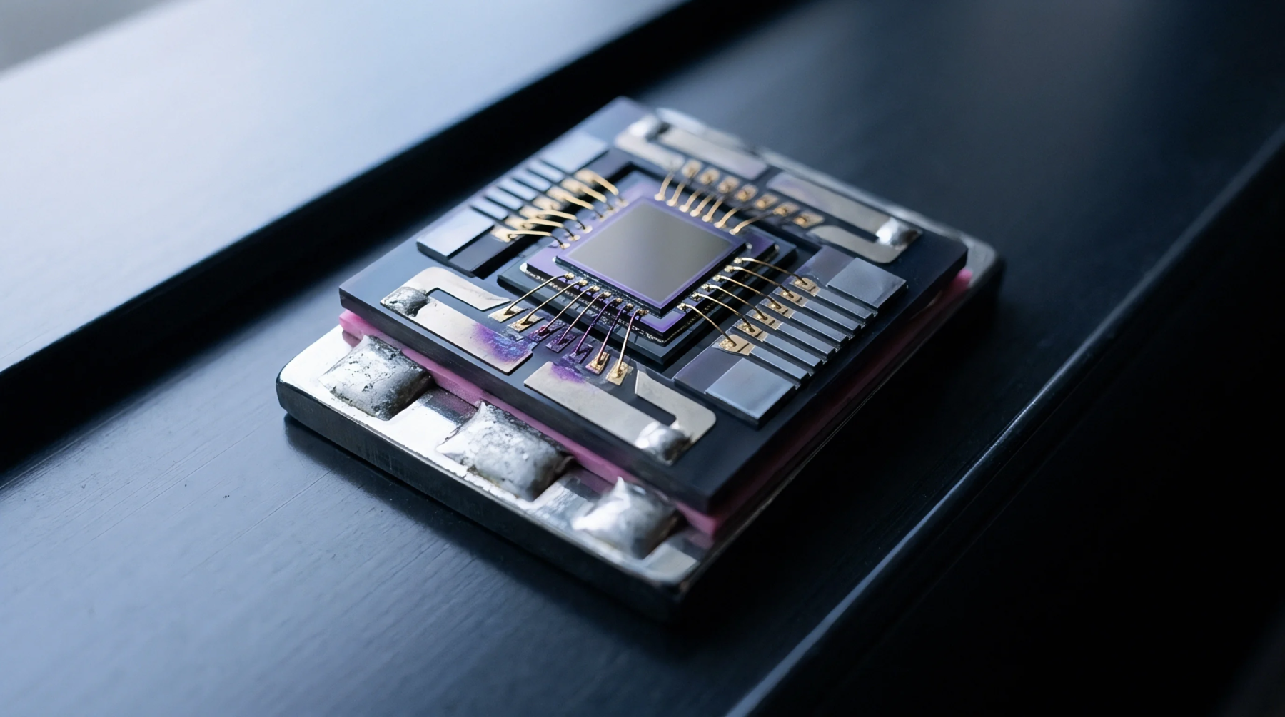
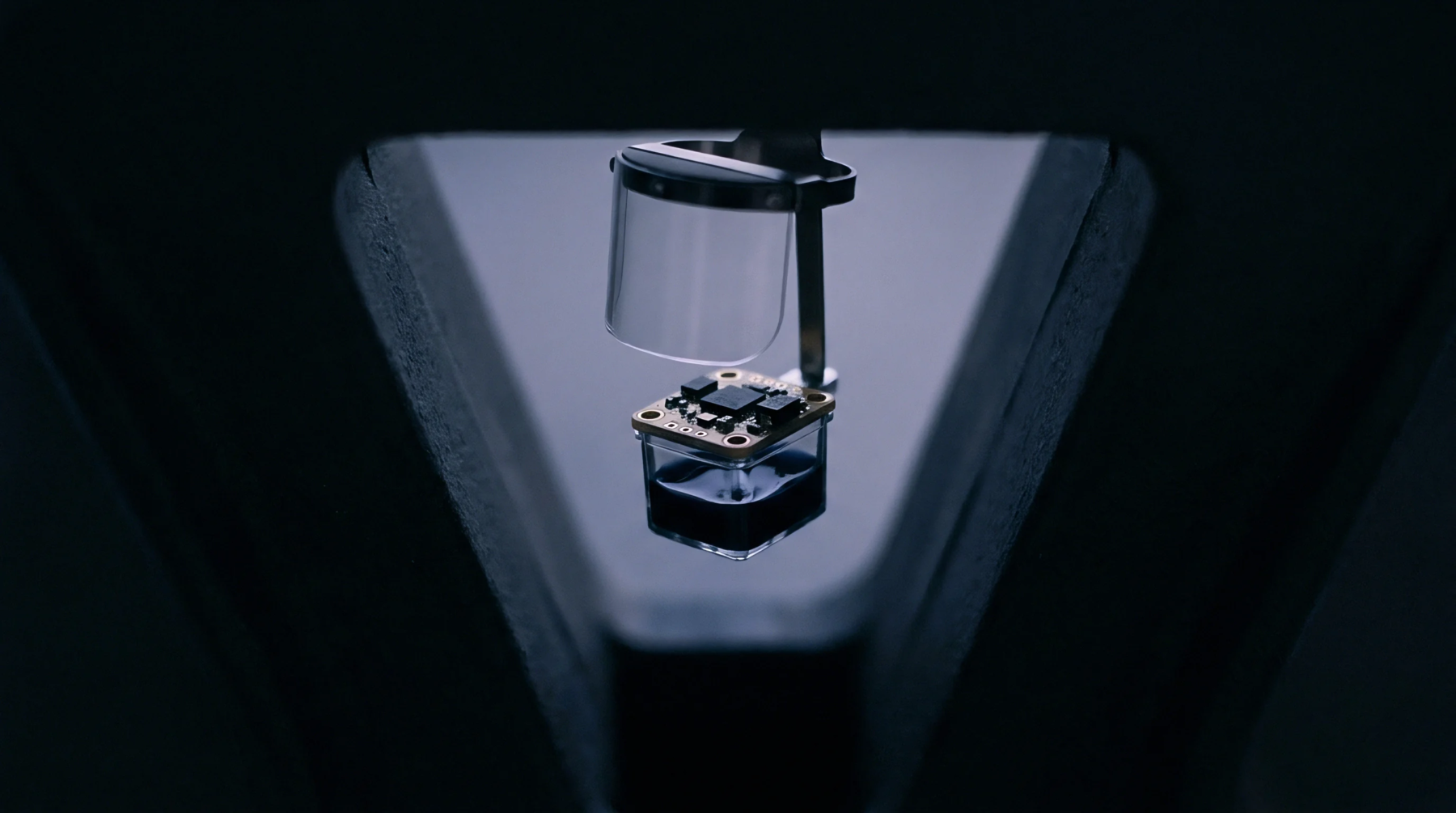
For silicon based devices, mismatch between the chip and its carrier leads to mechanical drift and signal inaccuracy. Standard values for common substrates like glass, copper and ceramic vary greatly and must be factored into every design. The parameter holds until the material reaches a phase transition or glass transition temperature where the behavior changes.
Reliability depends on keeping these thermal shifts within the elastic limits of the bond.
Reference Measurement
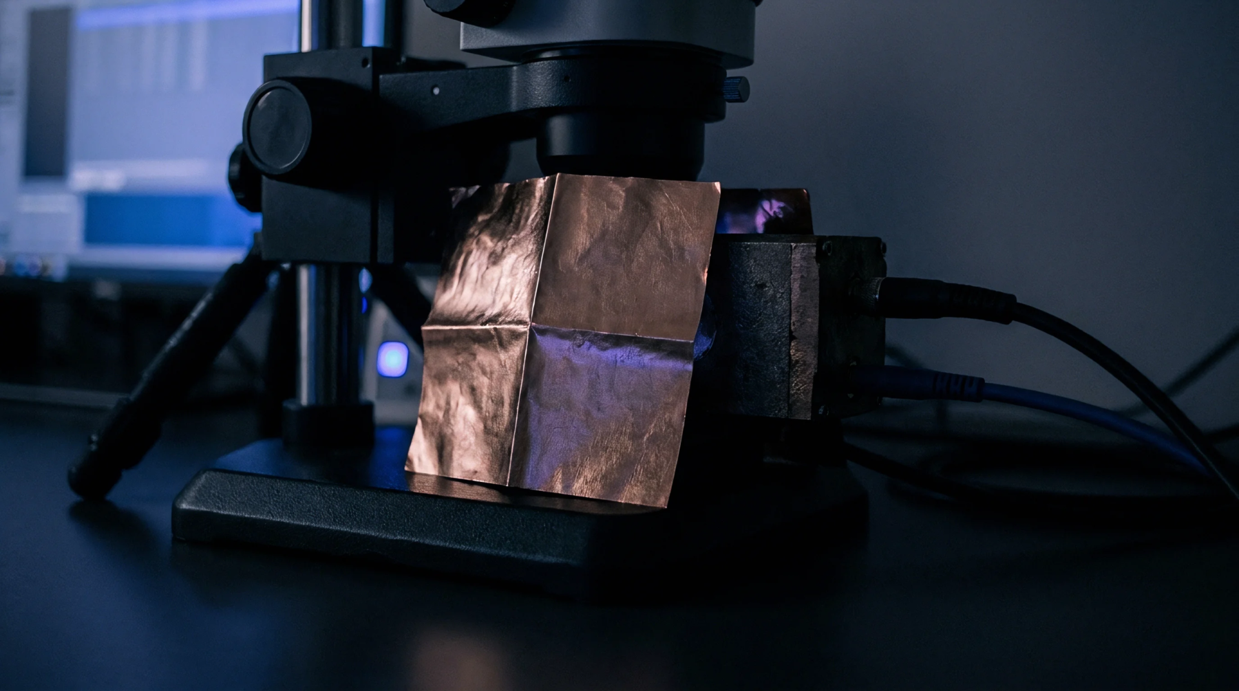
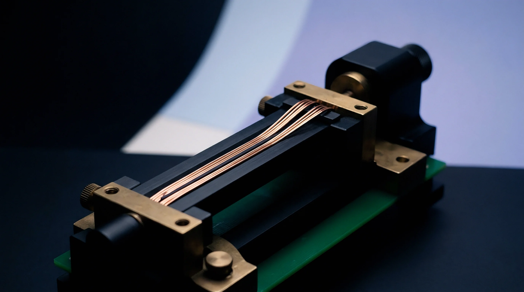
Metrological verification ensures that the reported values match the actual performance of the material inside the factory. To determine the coefficient of thermal expansion precisely, laboratories use dilatometry or thermomechanical analysis equipment. The test samples sit within a temperature controlled furnace while sensitive probes track micro fluctuations in their size.
Calibration of these probes involves using reference materials such as quartz or alumina with known stable properties. If the furnace temperature is not uniform, the result will contain an offset that misrepresents the material behavior. Accurate data allow for the simulation of joint stress between different layers of an integrated circuit.
Verification of these values usually occurs during the material qualification phase of sourcing. Traceability back to established physical constants provides the confidence needed for high reliability aerospace or medical applications.
Joint Interference
Stress distribution across multiple bonded interfaces depends on the proximity of the expansion values. When a high coefficient of thermal expansion material is forced against a low expansion substrate, the rigid interface acts as a pivot. This mechanism causes the assembly to bow or twist during wide temperature swings in the field.
Such deformation alters the gap in capacitive sensors or introduces false strain in resistive elements. Over many thermal cycles, the repeating strain eventually fatigues the interconnects or breaks the adhesive layers. Engineers specify tight tolerances for material choices to minimize these installation effects.
High drift in sensor output often signals a fundamental mismatch in the thermal properties of the surrounding enclosure. Frequent adjustments in assembly recipes might hide these problems temporarily without solving the mechanical root cause.
Installation Tolerance
Application constraints set the limits on how much expansion is tolerable before functionality is lost. Designers choose materials with a low coefficient of thermal expansion to maintain critical alignments inside optical or mechanical systems. If the expansion is too high, the lens could move out of focus or the gears could bind.
Sourcing departments seek batches of resins and metals that show consistency in their thermal behavior across multiple lots. When vendors change their raw stock, the expansion characteristics often shift slightly. This drift is measured at the component level to update the compensation algorithms in the internal software.
Regular checks confirm that the parts remain within the bounds defined by the specification sheets. Measurement accuracy remains constant as long as the temperature stays within the qualified operating range.