Thermal Response
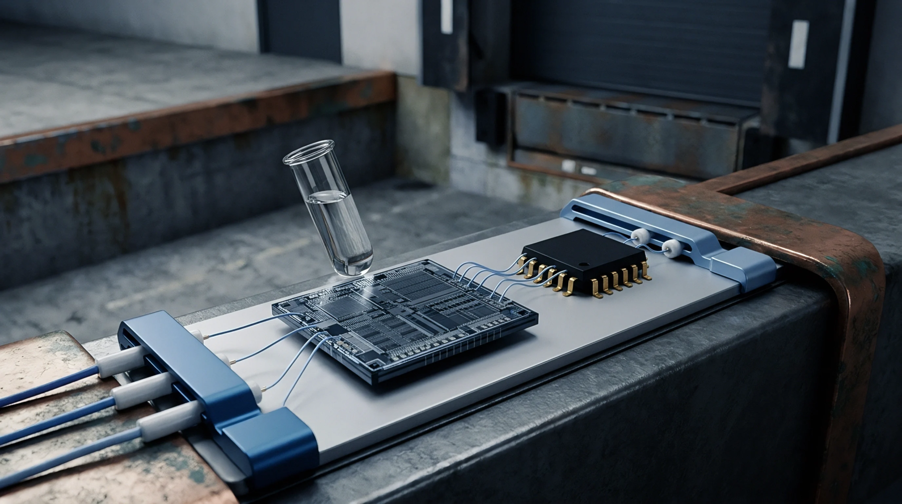
The thermal time constant defines the duration required for a sensing element to reach sixty-three percent of its final temperature step change under specified fluid dynamics and boundary conditions. This metrological metric governs how quickly a transducer registers an applied step function in temperature, operating as the primary design boundary for transient thermal acquisition. The parameter stops applying once internal temperature gradients within the sensor body become negligible compared to the surrounding medium resistance.
Metrologists use this constant to evaluate the speed of response across immersion assemblies, thermowells and bare junction sensors in flowing media. Calibration laboratories verify the value by plunging a stabilized probe from an ambient bath into a regulated fluid stream with a known velocity profile. Self-heating from excitation currents introduces a continuous measurement error that distorts the recorded transient profile during the test.
Radiation losses to chamber walls also degrade the accuracy of the transient data if emissivity differences between the sensor tip and the environment remain uncompensated.
Fluidic Loading
Convective heat transfer coefficients dictate the speed at which thermal energy transfers from the process fluid to the sensing boundary. Fluid velocity variations alter the convective film coefficient directly, changing the measured time constant without any alteration to the sensor itself. Viscosity shifts and density fluctuations in liquid streams introduce further variance into the nominal response calculation during field deployment.
Calibration certificates provide values established under ideal water or air velocities, which rarely match turbulent industrial process streams. Manufacturers establish tolerances under laboratory conditions, but field technicians frequently encounter installation effects that alter the local flow regime. Insertion depth into a pipe creates conduction errors along the stem, cooling the sensing junction and lengthening the apparent transient duration.
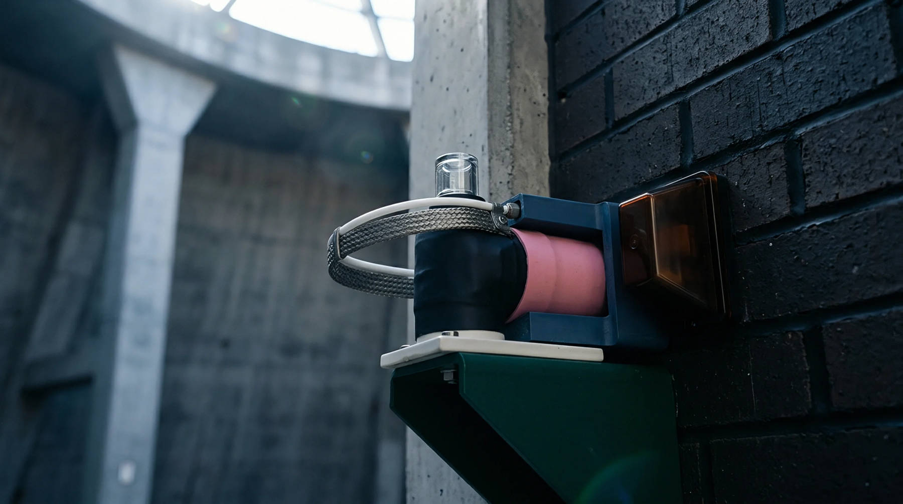
Protective thermowells add thermal mass to the assembly, multiplying the baseline duration of the bare element by a factor determined by wall thickness and material conductivity.
Junction Construction
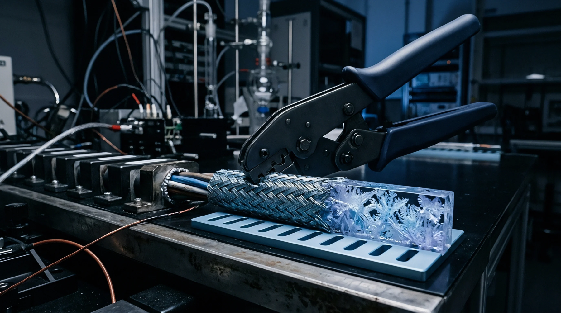
Internal thermal paths dictate the rate of heat flow from the sheath wall to the measuring junction inside the assembly. Mineral insulation powder packing quality determines how efficiently thermal energy transfers across the interior air gaps of a probe. Voids within this compacted oxide matrix create localized thermal resistances that delay the arrival of the step change at the sensing element.
Assembly techniques that eliminate moisture from the powder maintain the rated response speed over the operational lifetime of the device. Strain-relief mechanisms and mechanical mounting collars add parasitic mass near the tip, shifting the transient characteristics away from theoretical models. Differential thermal expansion between the sheath and the internal wires can alter the contact pressure at the junction, producing a permanent calibration shift after repeated thermal shock cycles.
Traceability Hierarchy
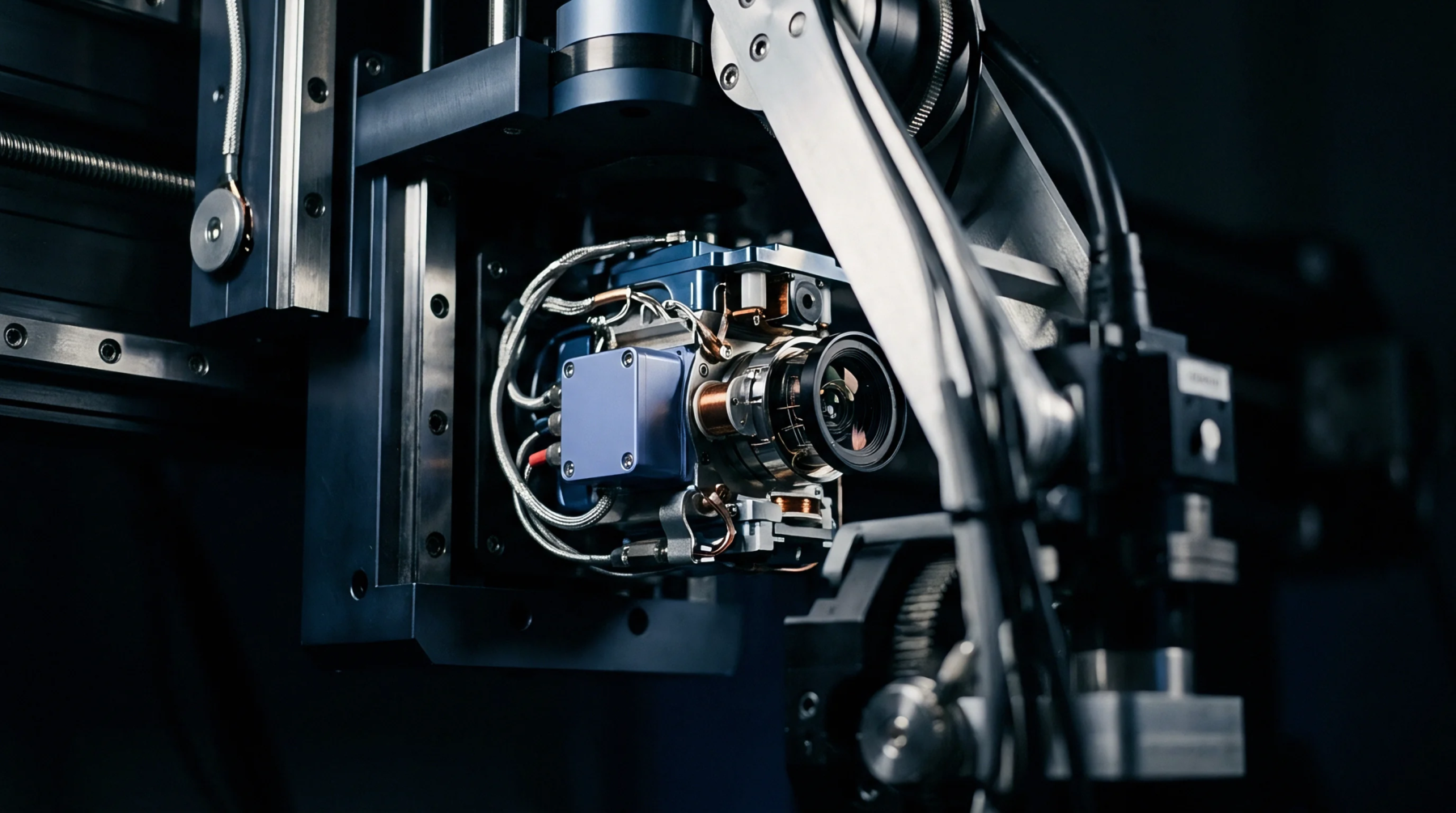
National standards laboratories maintain primary apparatus for step change verification using rapid insertion mechanisms into controlled water tunnels. Traceability flows from these primary facilities down to accredited calibration bodies through standardized reference probes and certified transfer standards. Industrial users verify their installed sensors against secondary references on the bench, noting any degradation caused by chemical attack or mechanical stress.
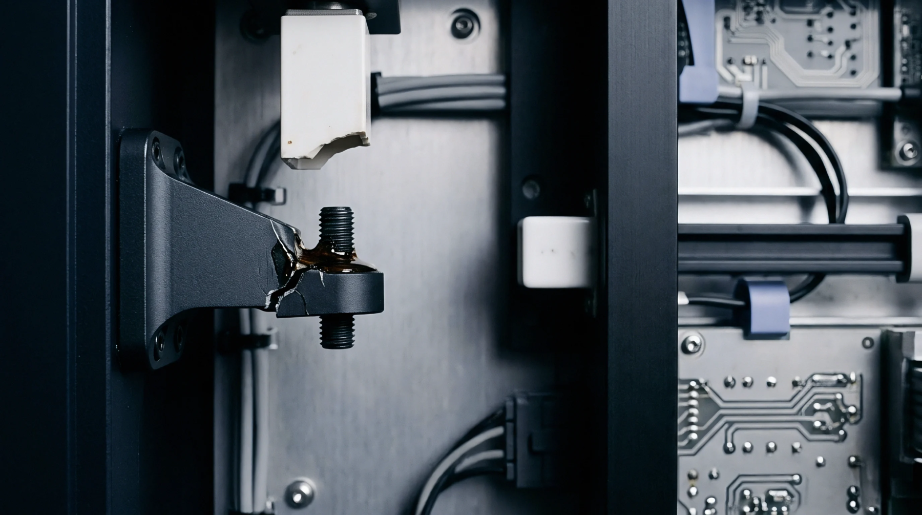
Sensor degradation manifests as a broadened transient curve because internal contamination alters the heat capacity of the measuring tip over time. Drift monitoring algorithms track changes in the thermal response alongside resistance shifts to predict impending sensor failure before catastrophic process shutdowns occur.