Substrate Piezoresistive Coupling Induced Baseline Shift under Dynamic Asymmetric Load Profiles
Dynamic asymmetric board strain couples into silicon piezoresistors via solder joints, causing uncompensated baseline drift mitigated by PCB isolation slots.

Warp
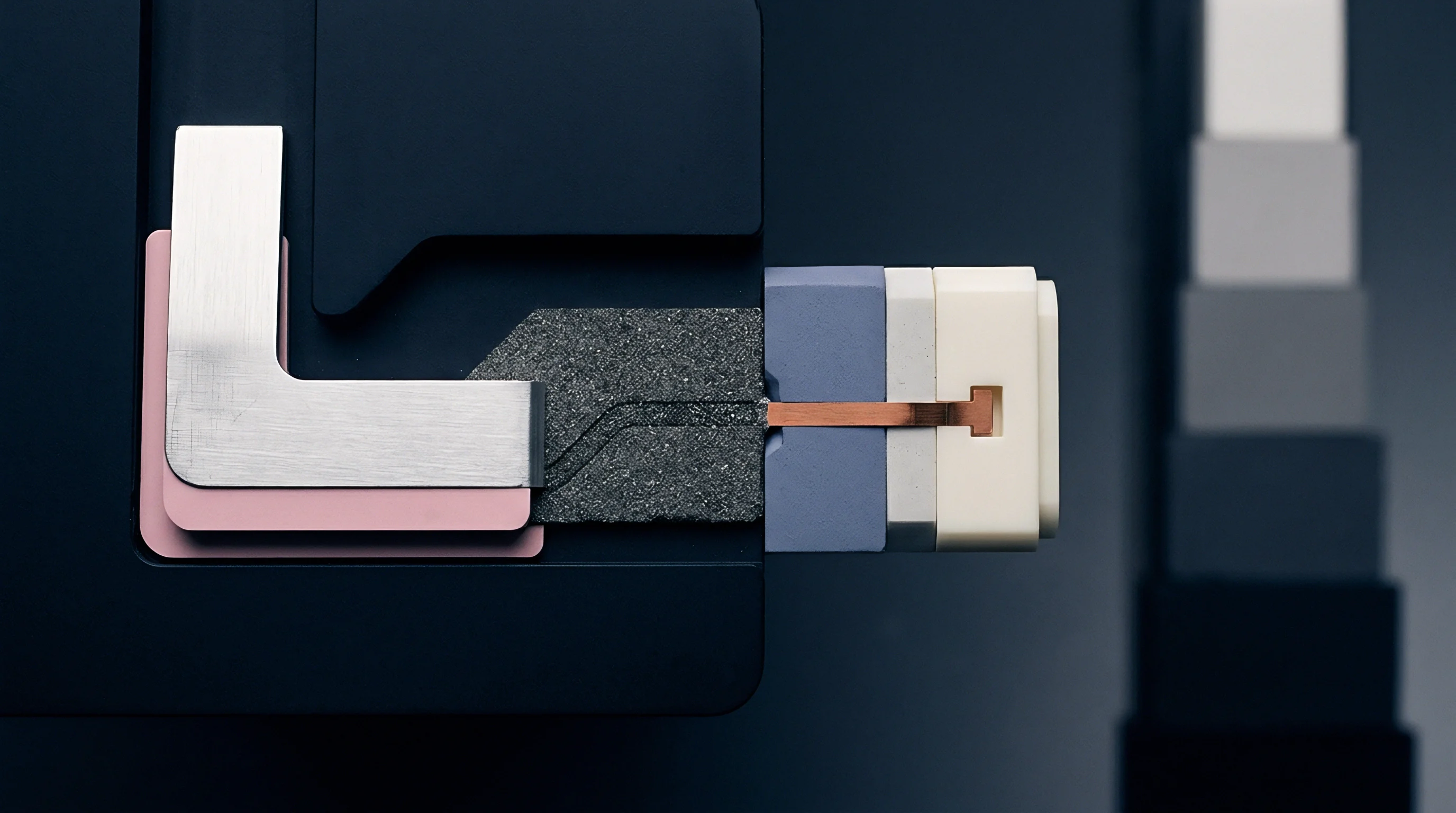
Surface-mount piezoresistive sensors rely on doped silicon to convert mechanical stress into resistance changes. When an external load bends the circuit board, strain propagates through copper lands and solder joints into the package mold compound, reaching the silicon die. Standard four-element Wheatstone bridges aligned with crystallographic axes on a (100) wafer surface cancel common-mode stresses under symmetric planar tension or compression.
Unbalanced bending breaks that symmetry. Dynamic, uneven moments across the package create spatial stress gradients across the die face that a standard bridge topology cannot cancel.
Board flexure concentrates strain beneath corner solder balls in land grid array and quad-flat no-leads packages. This differential strain across the resistor bridge shows up as a false signal, driving the bridge output voltage away from its zero-strain baseline and mimicking an actual physical pressure or acceleration reading.
A bridge circuit cancels uniform planar strain while converting shear gradients directly into uncompensated millivolt offsets.
Package geometry, substrate layer stackup, and die-attach modulus govern how much strain reaches the active silicon. A high-modulus epoxy die attach transfers up to 85 percent of substrate strain into the silicon region, while a compliant silicone adhesive keeps transmission below 20 percent. Encapsulant rigidity also influences mechanical transfer: molding compounds with high thermal expansion coefficients produce asymmetric stress fields across the die during cyclic flexing, locking a continuous offset into the analog front end.
Stress transfers across the package layers according to a few core variables:
- Substrate compliance dictates the baseline deflection radius of curvature under torsional loading.
- Solder joint standoff height changes the moment arm through which shear forces enter the package base.
- Die attach thickness controls the shear strain distribution profile across the bottom of the silicon.
- Silicon crystallographic orientation sets the piezoresistive coefficients linking directional stress tensors to resistance shifts.
Thicker solder joints cushion the die by attenuating board strain before it reaches the silicon.

Hysteresis
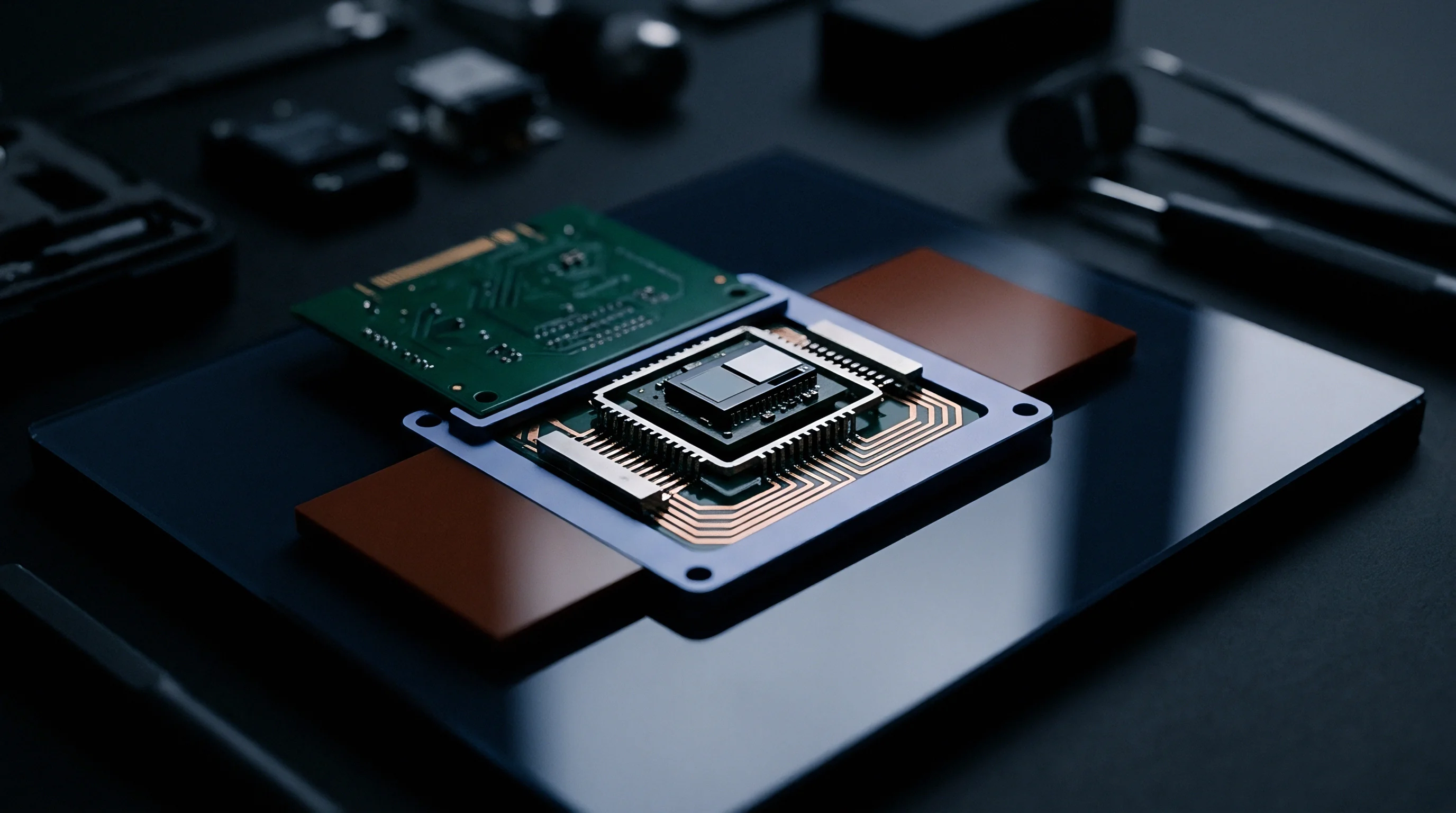
Asymmetric loading cycles cause time-dependent baseline drift due to viscoelastic creep in organic packaging materials. Standard glass-reinforced FR4 laminates exhibit mechanical hysteresis when flexed repeatedly. When deflection cycles carry uneven dwell times or directional bias, the polymeric matrix within the FR4 laminate fails to recover its resting geometry immediately upon load removal, leaving residual strain that takes hours or days to decay.
Solder joints also undergo localized plastic deformation under dynamic cyclic loading. Lead-free alloys such as SAC305 form microstructural dislocation slip planes when subjected to repeated asymmetric strain amplitudes above 0.2 percent. Because this plastic strain persists after unloading, residual stress remains trapped in the package corners, permanently re-biasing the silicon piezoresistors.
| Alloy Composition | Yield Strength (MPa) | Creep Rate at 25C (1/s) | Residual Strain (%) | Zero-Point Shift (mV/V) |
|---|---|---|---|---|
| Sn63Pb37 | 38.2 | 2.1e-6 | 0.045 | 0.12 |
| SAC305 (Sn96.5Ag3.0Cu0.5) | 44.8 | 8.5e-7 | 0.082 | 0.28 |
| SAC405 (Sn95.5Ag4.0Cu0.5) | 48.1 | 6.2e-7 | 0.095 | 0.34 |
| Sn42Bi58 | 56.0 | 1.2e-5 | 0.031 | 0.09 |
| Sn99.3Cu0.7 | 32.0 | 3.4e-6 | 0.061 | 0.19 |
As these materials slowly relax, the sensor baseline drifts toward the dominant load bias. Repeated flexing along a single axis ratchets the baseline upward or downward with each consecutive cycle. Thermal swings compound this ratcheting by altering the viscoelastic relaxation modulus of the epoxy underfill and mold compound.

Do Thermal Fluctuations Accelerate Drift?
Temperature swings alter the glass transition state of packaging polymers. Above that transition point, polymer chains move far more freely, driving up creep rates under steady mechanical bias. Stress relief through solder recrystallization during temperature dwells occurs unevenly across the die perimeter, preventing the sensor from recovering its original factory-calibrated zero-load reading.
Uncalibrated baseline drift leads directly to false event triggers, degraded system accuracy class ratings, and premature field replacements in precision instrumentation.

Register
Digital sensor interfaces hide underlying mechanical stress until bridge offset consumes the input dynamic range of the internal analog-to-digital converter. Integrated pressure and force sensors package a piezoresistive MEMS die alongside an ASIC containing programmable gain amplifiers, an analog-to-digital converter, and DSP correction engines. Factory calibration trims the zero-load offset at 25 degrees Celsius, storing correction coefficients in non-volatile EEPROM registers.
Substrate flexure introduces a differential voltage into the analog front end, amplifying the mechanical error alongside the intended signal. If this baseline shift pushes past the front-end clipping threshold, the output register clamps at full scale, regardless of digital compensation math.
A factory digital calibration register holds no validity once board-level mechanical assembly alters the zero-load analog input voltage by more than three millivolts per volt.
Host firmware reads corrupted baseline values over I2C or SPI buses. The physical communication sequence operates as follows:
- The host microcontroller asserts the chip select line and issues a read command to the 16-bit primary data registers located at address offsets 0x06 and 0x07.
- The sensor ASIC clocks out raw conversion bytes while an internal low-pass filter averages transient mechanical noise, concealing rapid strain spikes from the bus transaction.
- Baseline tracking routines in firmware compare the returned count against an initialization threshold stored in host flash memory.
- When board flexure induces a static offset exceeding the permissible auto-zero window, the tracking routine flags a calibration fault and rejects the measurement.
Some smart sensor ASICs run internal auto-zero algorithms periodically, but these routines assume zero external load during execution. If an asymmetric mechanical load remains active on the housing when the auto-zero routine fires, the ASIC registers the board-flex strain as the new reference zero. Once the external load releases, the sensor outputs a negative offset equal to the mechanical strain present during calibration.
Customer-reported baseline drift frequently traces to unsupported structural mounting or solder reflow profiles outside specified peak heating windows.


Layout
PCB layout serves as the primary defense against mechanical strain propagation. Trace routing, copper pour balance, board thickness, and mechanical relief routing govern how chassis torsion travels into component terminals. Placing a piezoresistive sensor package at the geometric center of a large, unsupported circuit board exposes the die to maximum bending deflections during push-button actuation or enclosure flexure.

Where Should Relief Slots Be Positioned?
Routing mechanical isolation slots around three sides of the sensor footprint decouples the land pattern from global board torsion. A routed slot measuring 1.0 mm wide forces stress paths around the perimeter of the sub-island, reducing strain transmission to the die by 18 dB to 24 dB. In high-vibration enclosures, slotting prevents low-frequency chassis modes from driving offset fluctuations.
| Footprint Isolation Configuration | Strain Transmission Factor | Peak Shear Stress (MPa) | Zero Shift (Percent FSO) | Board Area Added (mm²) |
|---|---|---|---|---|
| Solid Board Without Relief (Reference) | 1.00 | 14.2 | 3.85 | 0.0 |
| Dual Parallel Routed Slots (0.8 mm width) | 0.34 | 4.8 | 1.31 | 12.5 |
| Three-Sided U-Shaped Relief Slot | 0.11 | 1.6 | 0.42 | 24.0 |
| Corner Relief Drill Holes (4x 1.2 mm) | 0.68 | 9.7 | 2.62 | 8.0 |
| Separate Interposer Daughtercard | 0.02 | 0.3 | 0.08 | 64.0 |
Balanced copper distribution across inner substrate layers suppresses asymmetric warping during thermal excursions. Symmetrical ground and power planes prevent bi-material plate bending under operating thermal gradients. Keep-out zones around the sensor prohibit large electrolytic capacitors, heavy connectors, or mounting screws within a 5.0 mm radius.
Overtightened fasteners distort the local FR4 laminate profile. Solder mask defined land patterns provide consistent copper pad areas, establishing uniform solder fillet geometries that balance anchor forces across package terminations.
IPC-7351 guidelines recommend nominal land protrusion dimensions, but isolating piezoresistive packages from mechanical substrate strain demands minimum pad geometries to reduce solder joint contact area.
Section 4.2 of IPC-A-610 specifies maximum allowable PCB bow and twist tolerances at 0.75 percent for surface-mount assemblies, a limit that still permits sufficient out-of-plane curvature to generate intolerable baseline shifts in sensitive piezoresistive bridges.
Cost
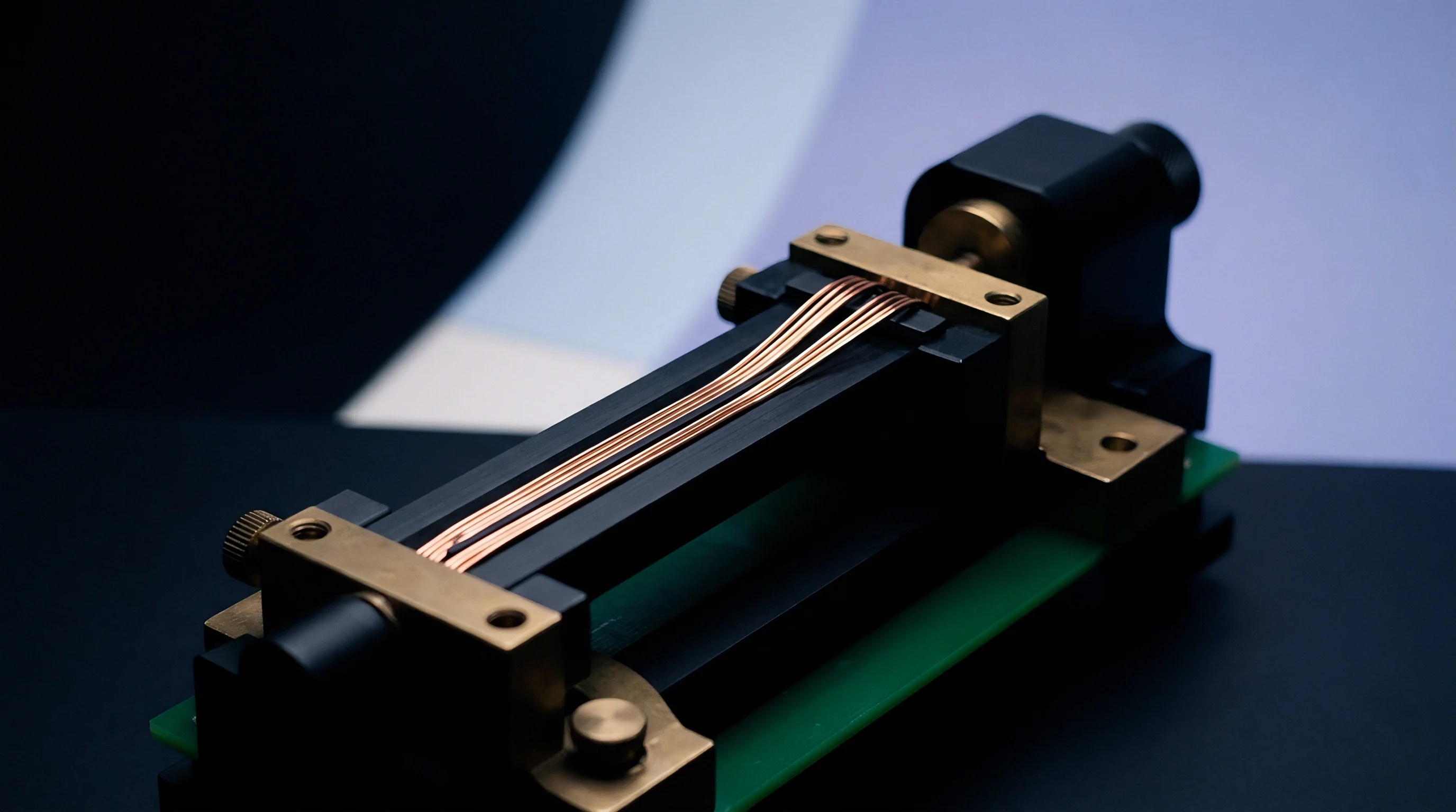
Mitigating substrate strain involves clear cost trade-offs across package selection, production yield, and engineering bring-up hours. Bare silicon dies mounted directly onto circuit boards via chip-on-board wire bonding offer the lowest component unit price, yet they demand high board layout precision and compliant potting steps that increase production cycle time. Molded surface-mount packages integrate preliminary mechanical isolation, but transfer substrate strain through rigid solder balls.
Fully isolated standalone modules incorporate an internal gel-filled cavity and a separate mechanical header that completely isolates the piezoresistive die from external mounting forces. This construction eliminates baseline drift under dynamic asymmetric load profiles, but increases unit costs significantly.
| Packaging Format | Unit Price at 10k Volume (USD) | Board Space Required (mm²) | Assembly Line Yield (%) | Firmware Integration Weeks | Drift Susceptibility Index |
|---|---|---|---|---|---|
| Bare Die (Wire Bond) | 0.85 | 4.2 | 94.2 | 6.0 | 0.92 |
| QFN / LGA (SMD) | 1.65 | 9.0 | 98.8 | 3.0 | 0.65 |
| Ceramic Interposer Substrate | 3.20 | 16.0 | 99.1 | 2.5 | 0.28 |
| Isolated Gel-Filled Module | 6.40 | 45.0 | 99.7 | 1.5 | 0.04 |
| Hermetic Header (Cabled) | 14.80 | 120.0 | 99.9 | 1.0 | 0.01 |
Firmware-based baseline compensation reduces hardware expenses, but extends software validation schedules. Dynamic filtering and running baseline estimation require testing across thousands of physical load profiles to ensure real pressure signals are not erroneously filtered out as substrate warpage. When production volume surpasses 100,000 units annually, implementing mechanical routing slots on a standard SMD package offers the lowest overall landed manufacturing cost.
System designs ultimately balance the combined bill of materials, circuit board real estate, and calibration cycle times across the complete operating life of the final product.